Gameboy Zero
This article is still a WIP
Although I never really played games growing up or had any consoles, I have always been interested in retro gaming, especially handheld gaming. Around 2016 I decided I wanted to build my own handheld gaming console.
Inspiration
There are a lot of examples where people have built their own all-in-one handheld GameBoy. Below is a list of examples I got ideas from.
Prototype (Finished June 2019)
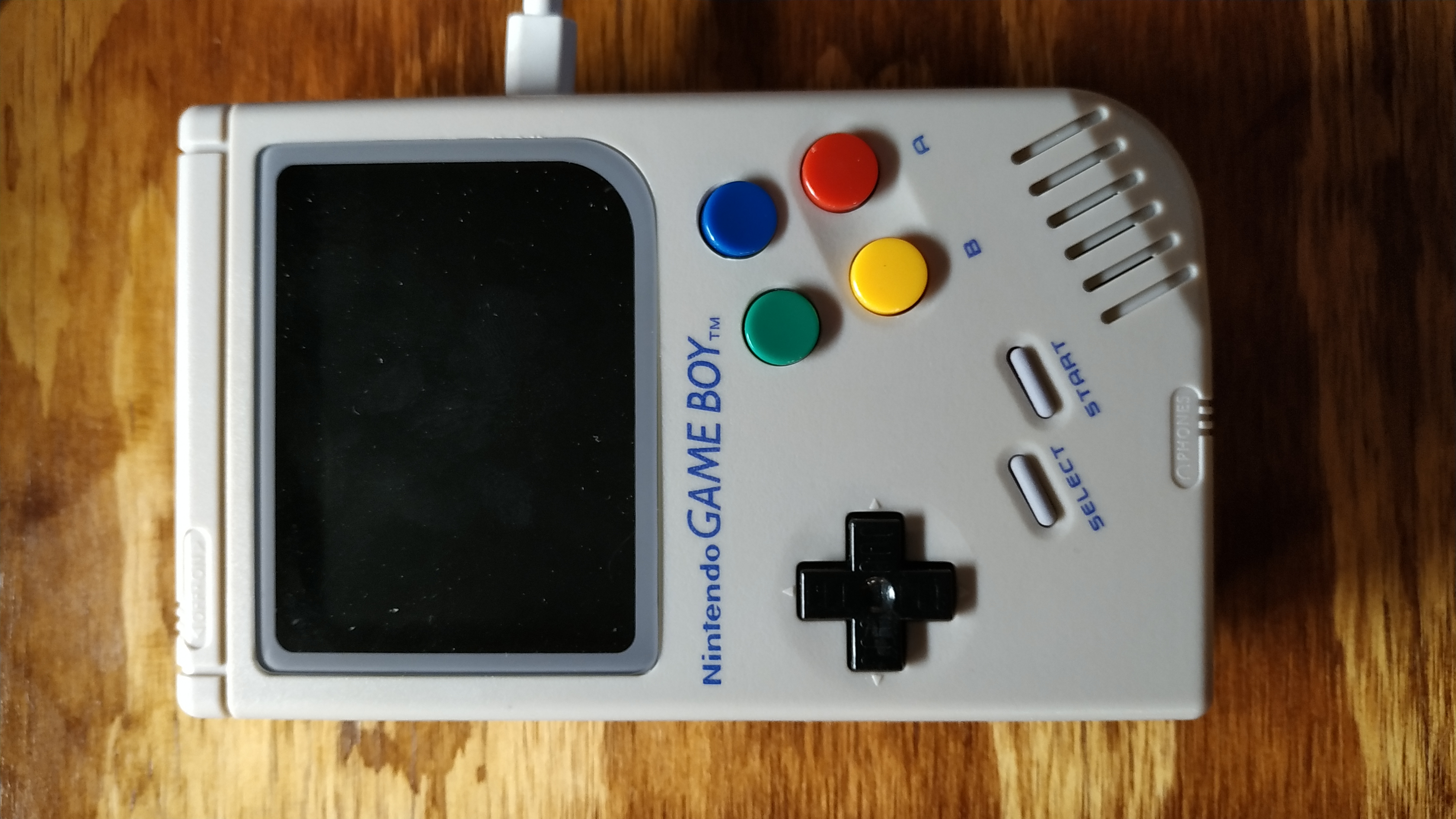
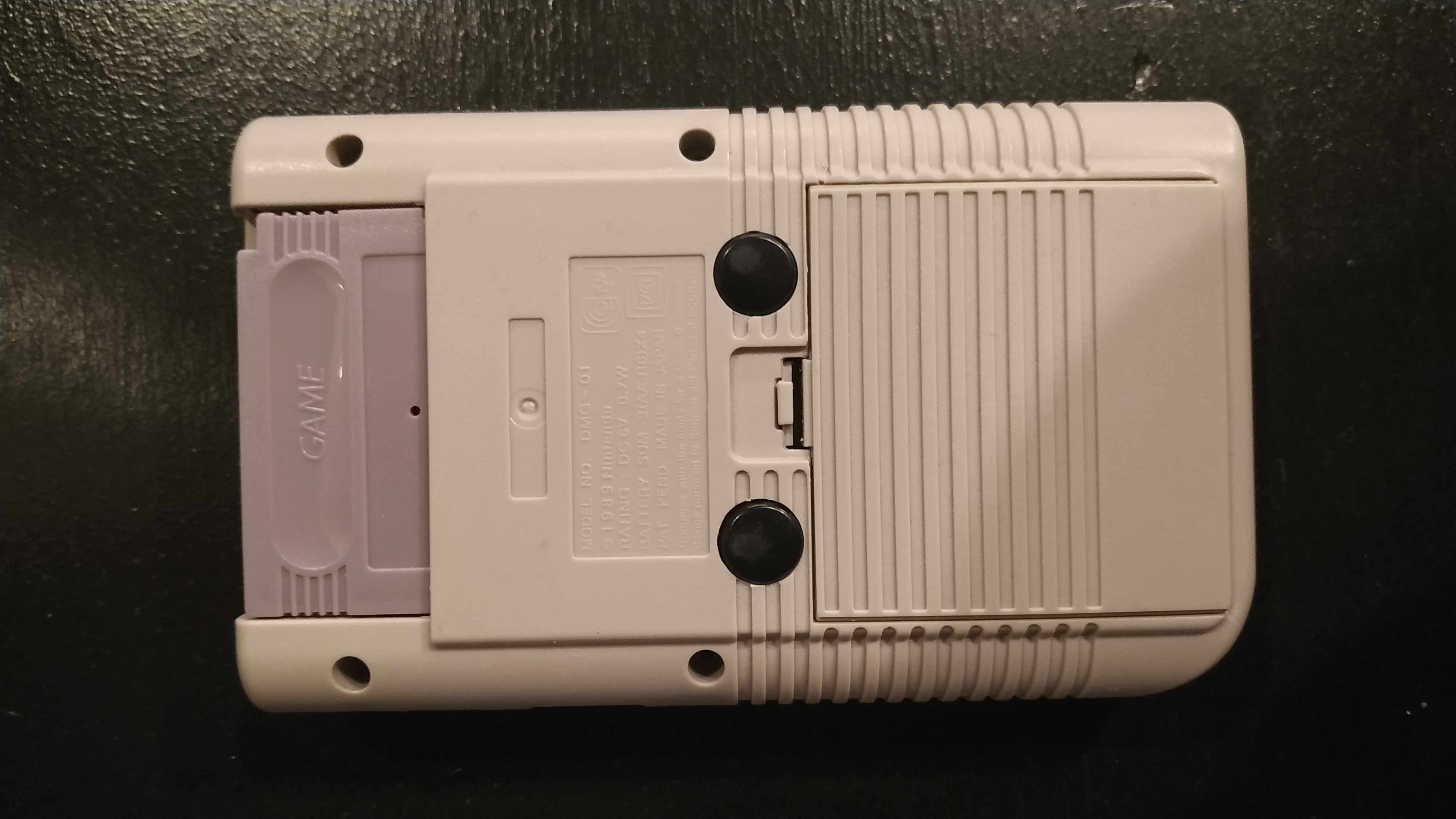
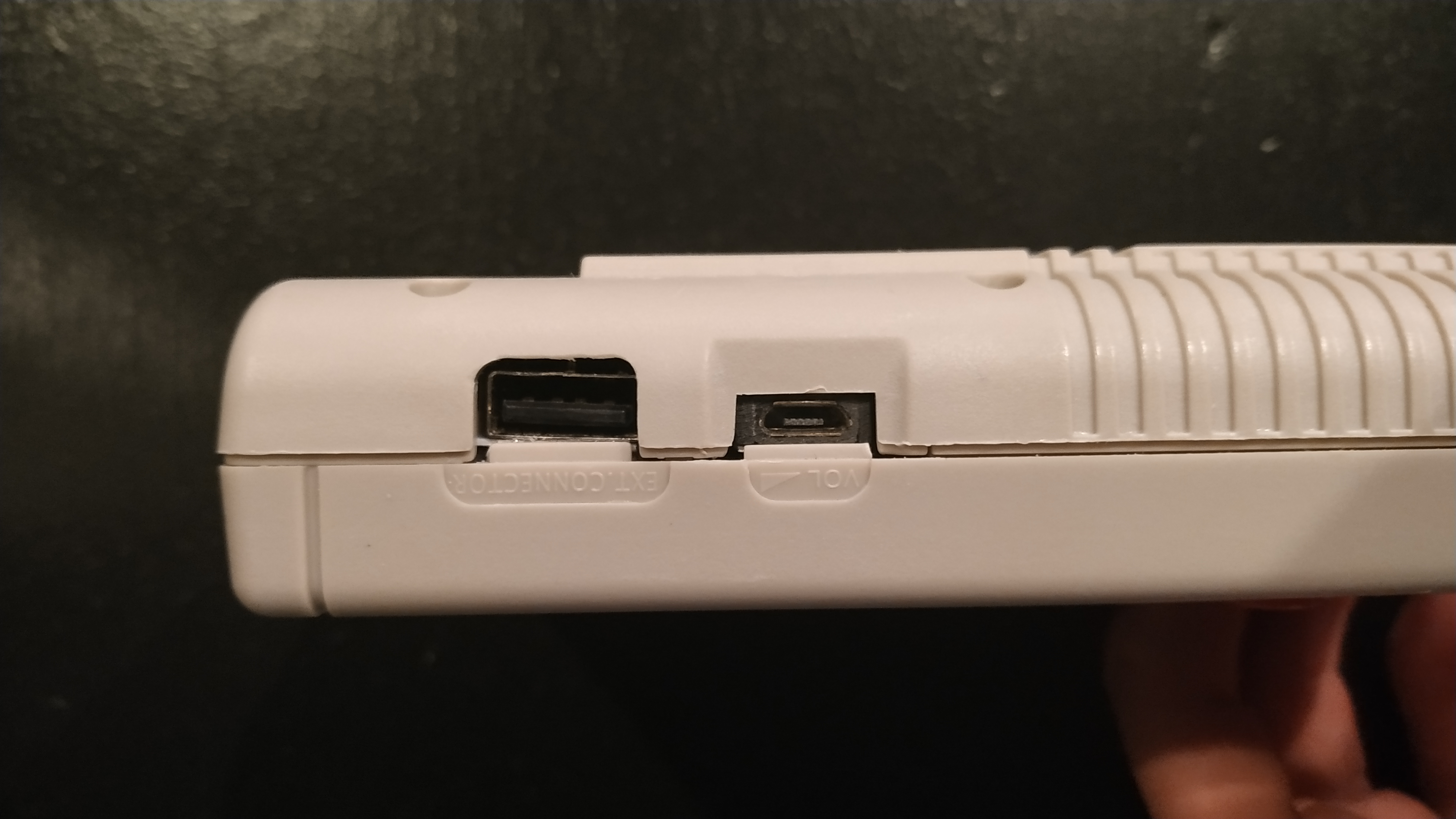
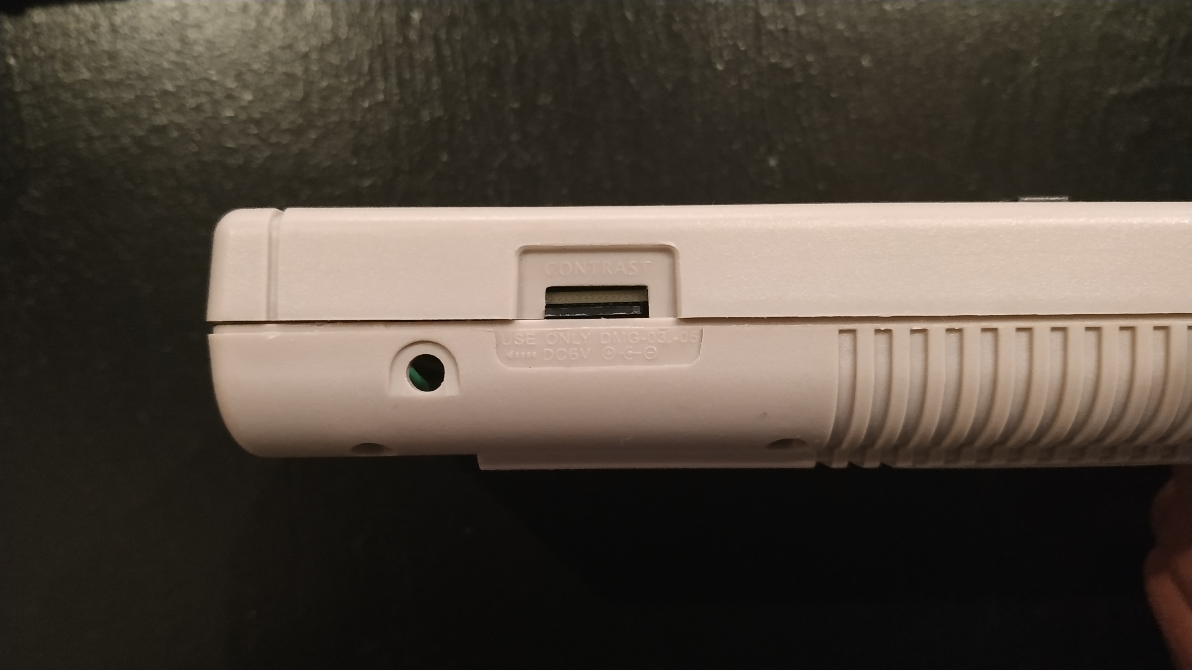
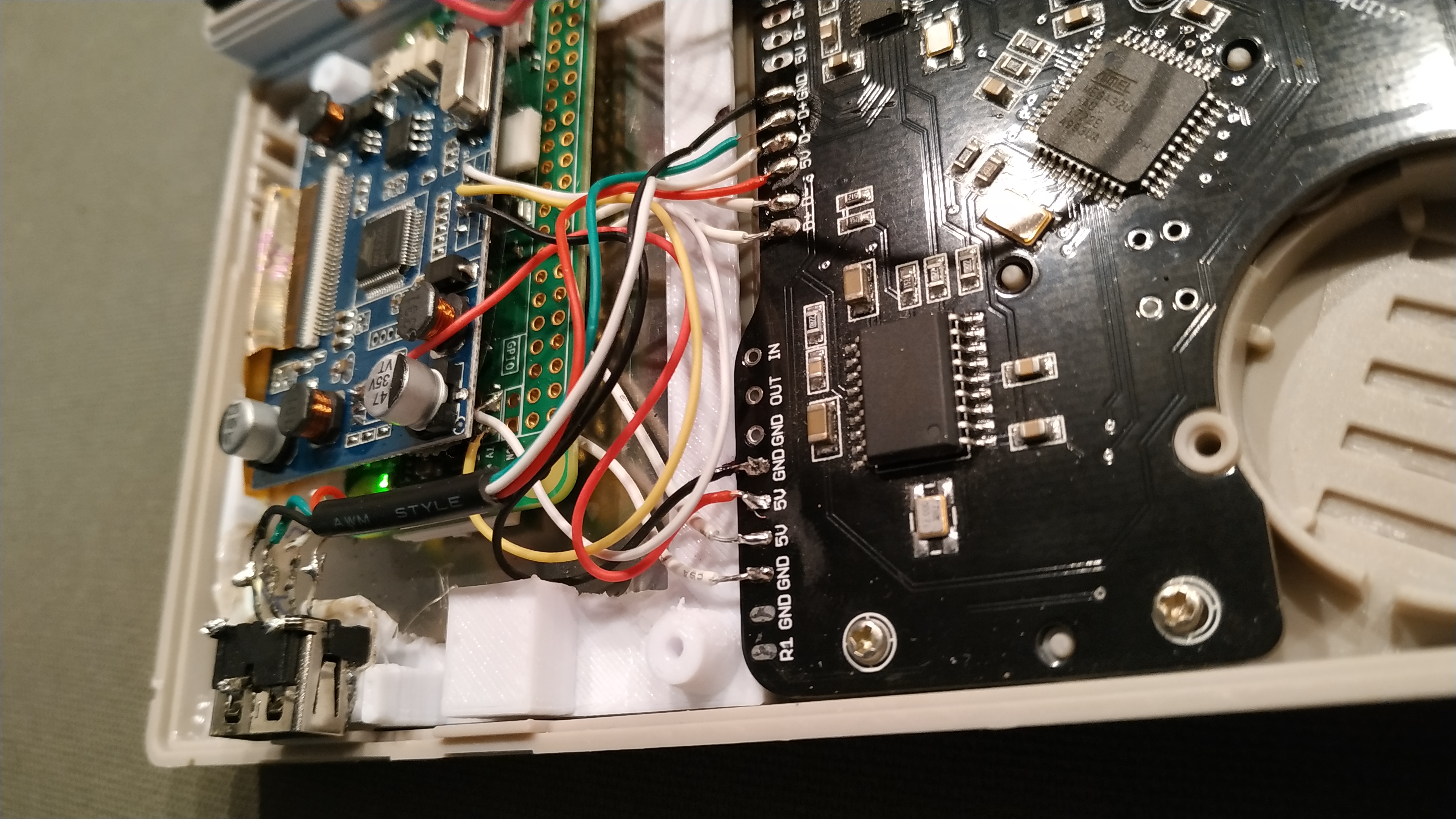
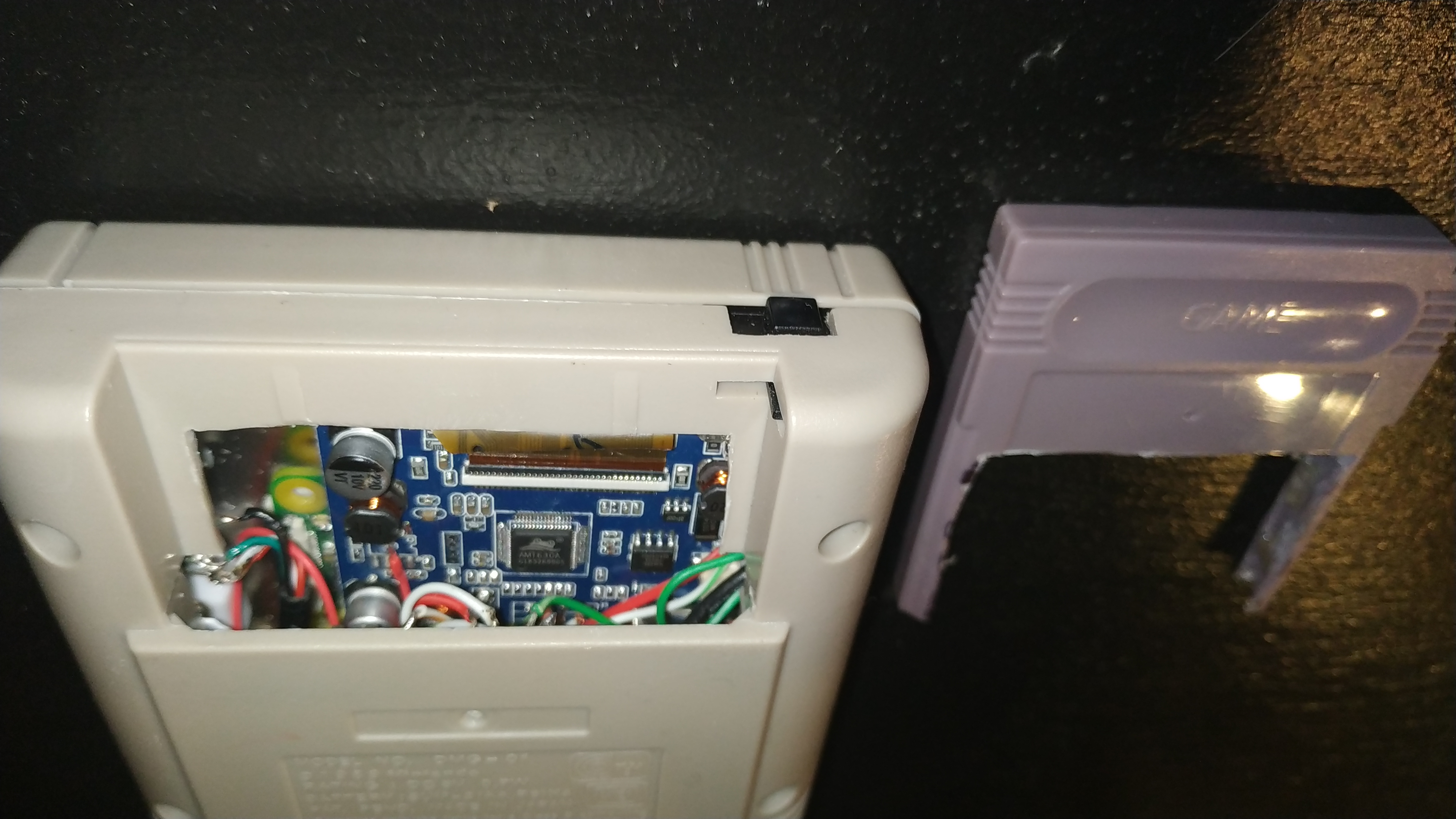
The first build I did was less of a prototype and more of a hand-wired mess crammed into an aftermarket Nintendo Gameboy DMG-01 case.
Hardware
| Purpose | Part | Explanation |
|---|---|---|
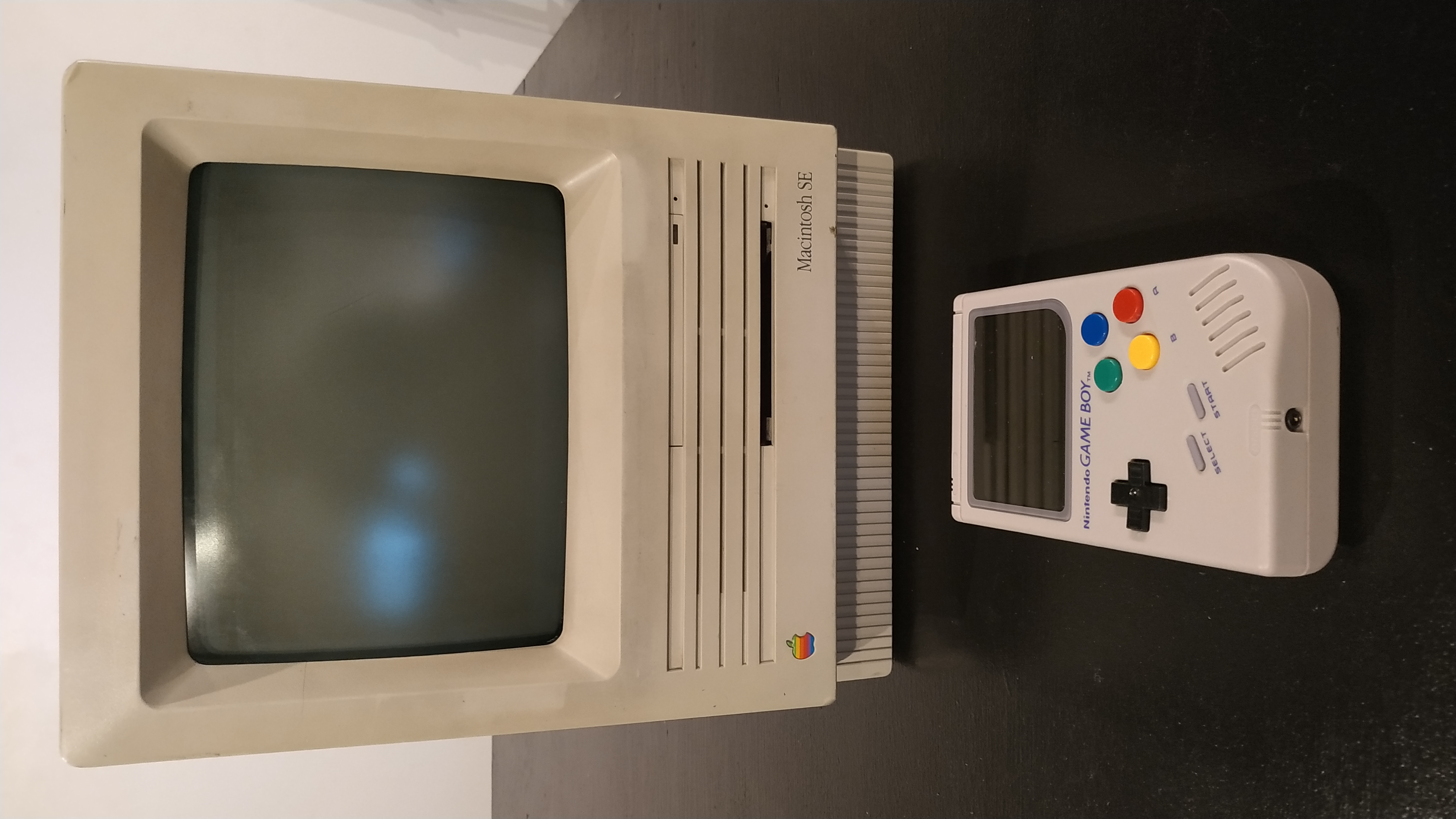
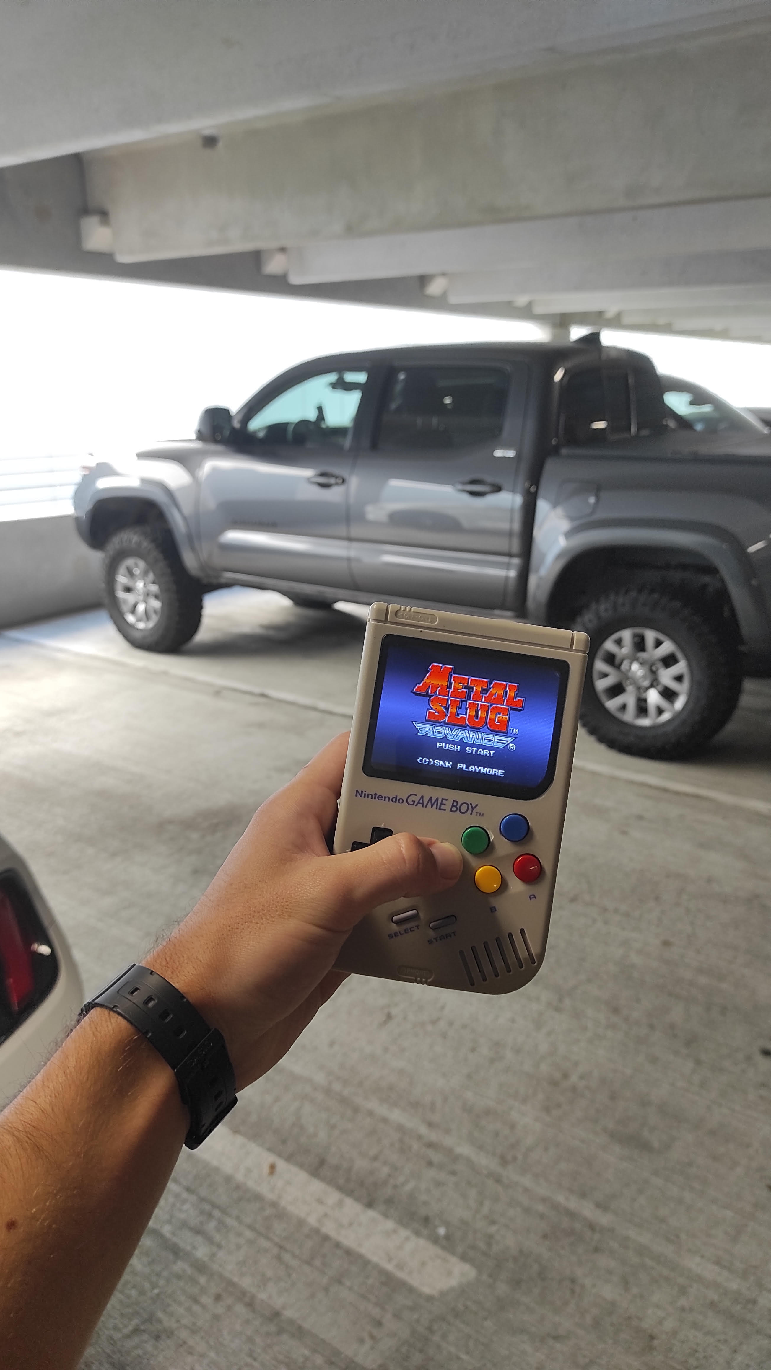
| Case & Buttons & Glass | Galaxy Gaming Super Famicom | OG Gameboy remanufactured case with super Famicom colored buttons |
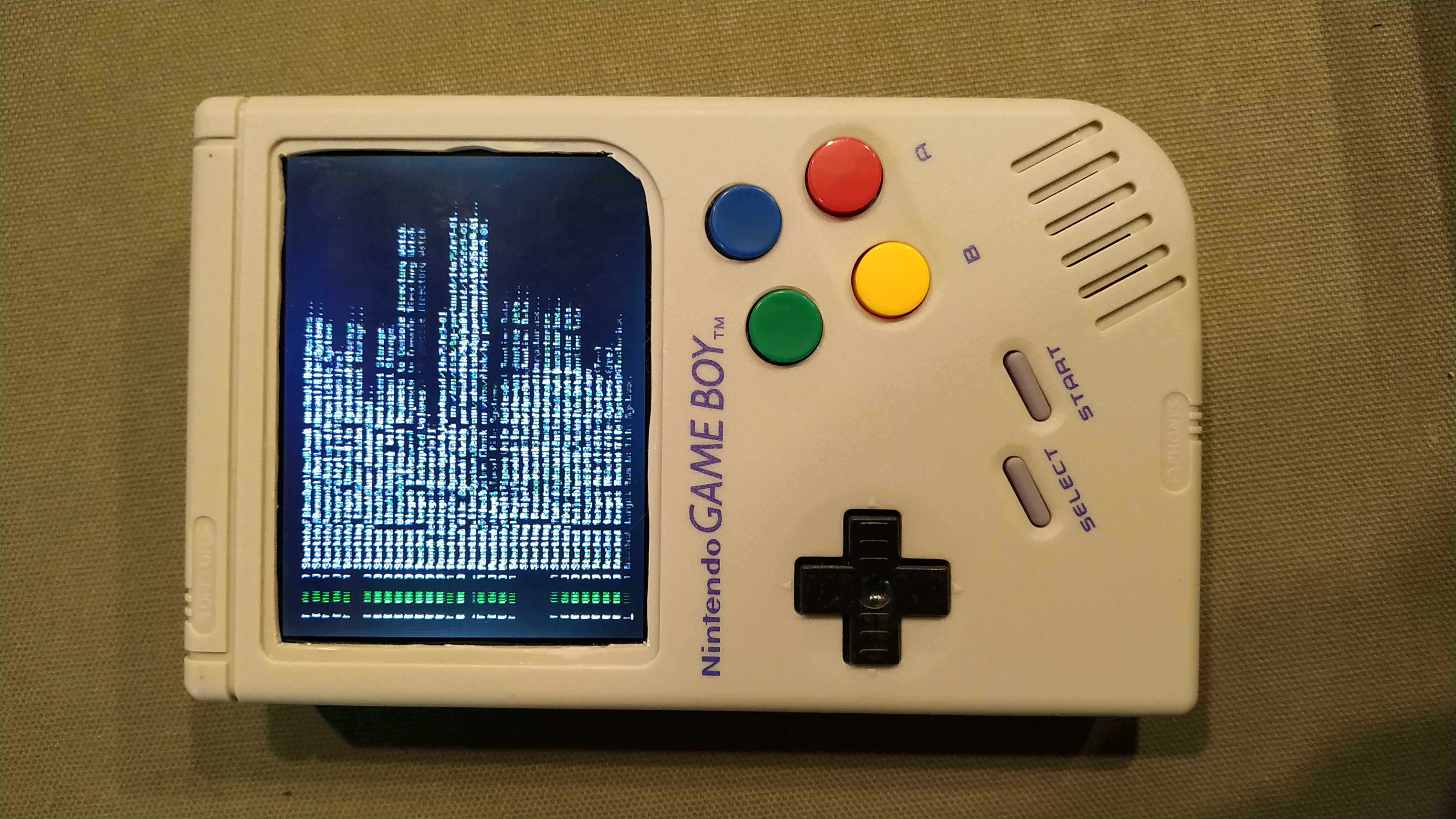
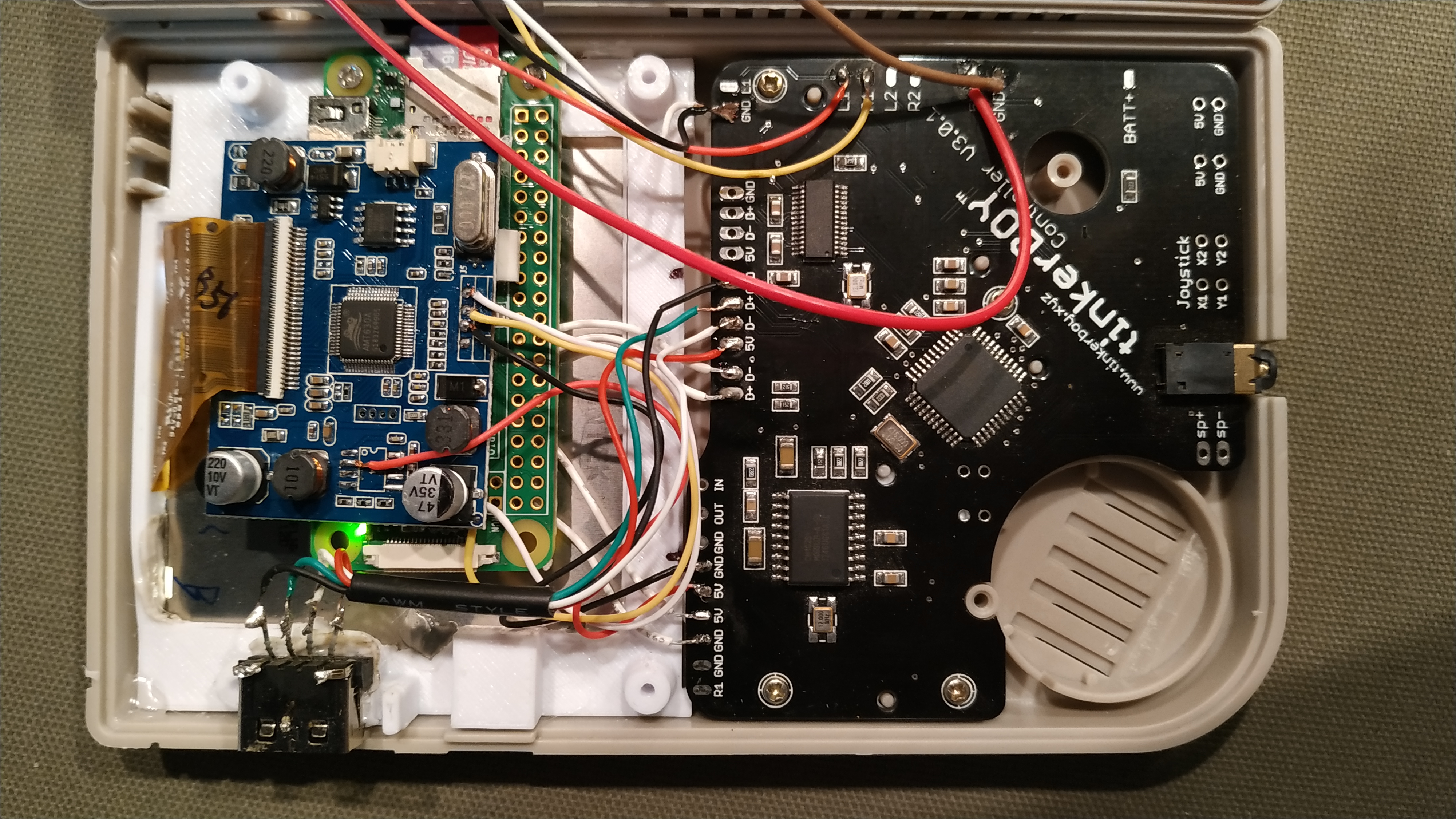
| Brain | Raspberry Pi Zero | The raspberry Pi zero is a very cheap single-board ARM computer capable of running Linux |
| Screen | Cheap Amazon 3.5" composite car screen | This screen is quite popular for these and other raspberry pi projects since it is so small. Modded to accept 5V instead of 12V |
| Buttons | Tinkerboy AIO Controller v3.0.1 | |
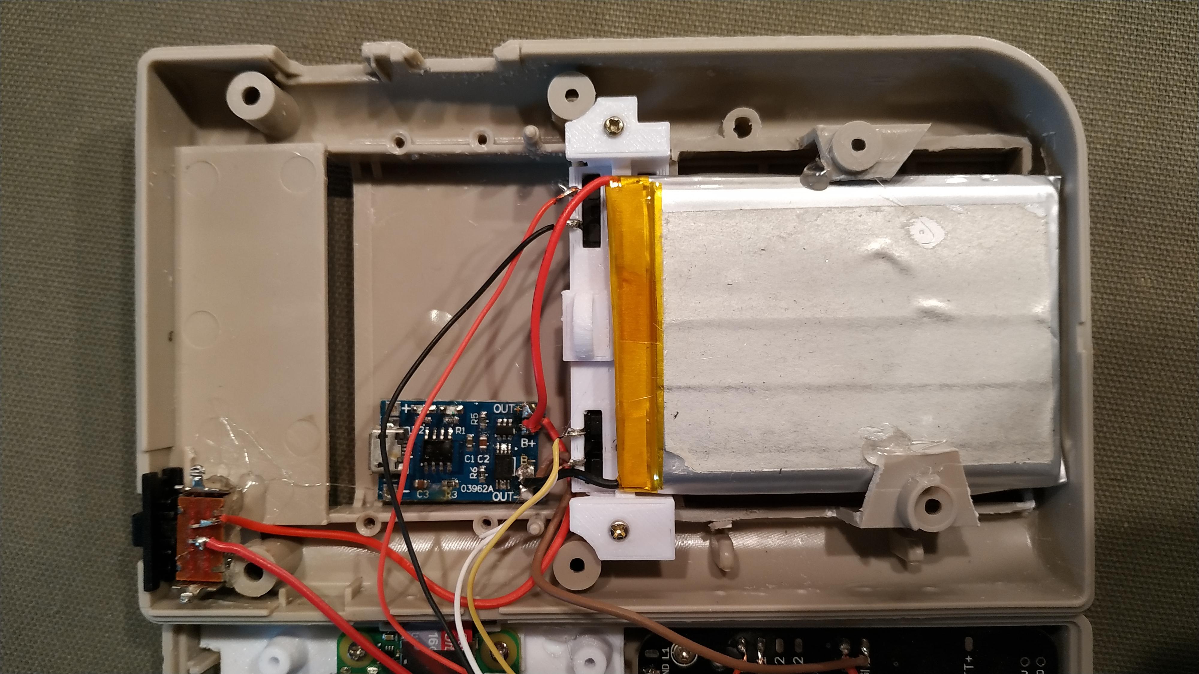
| Battery | 3 1000mAh Li-ion phone batteries in parallel to create 3000mAh | |
| Power | Adafruit Powerboost 1000c | Handles power delivery and battery charging |
Software
| Purpose | Description |
|---|---|
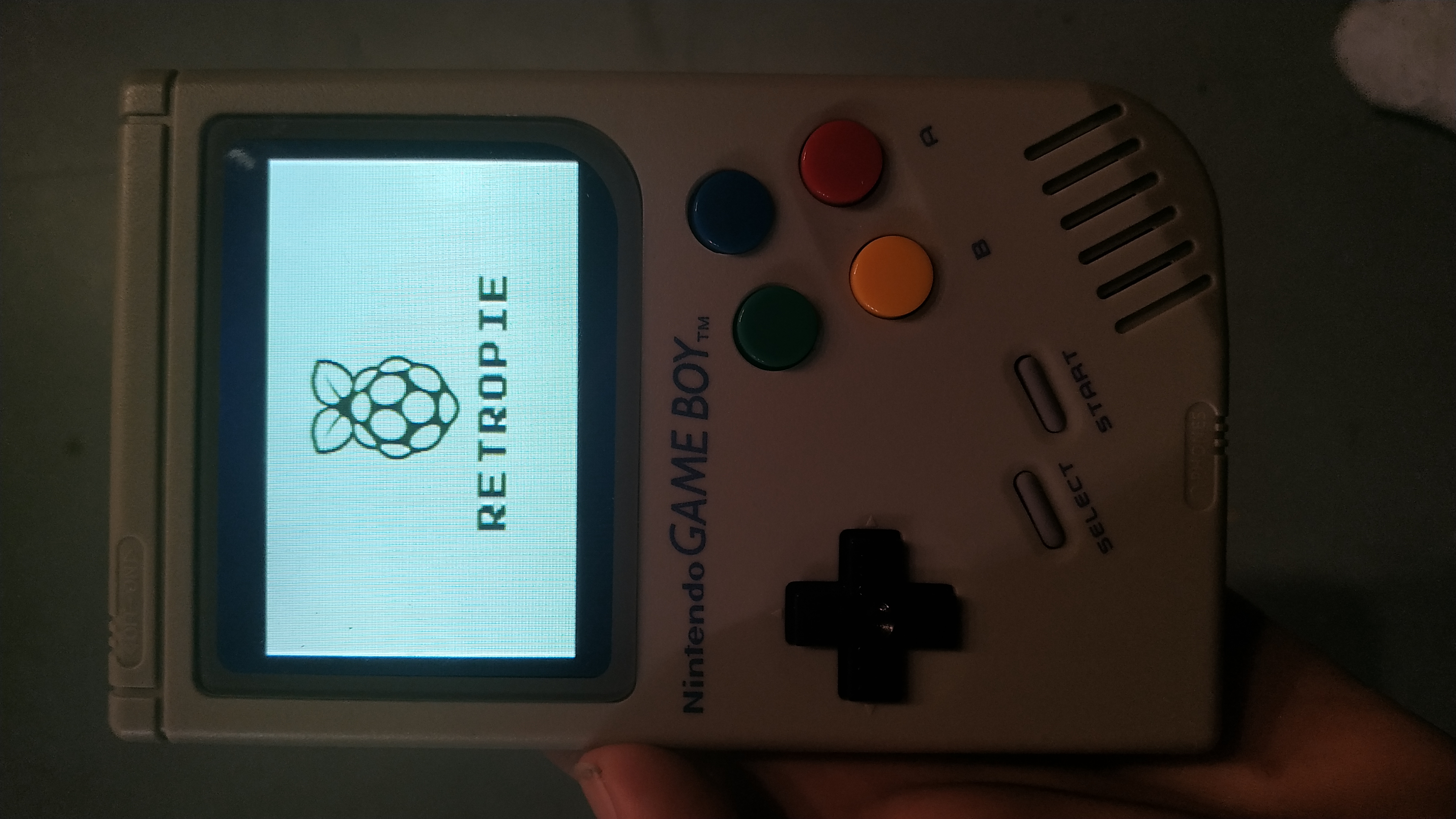
| Operating System | RetoPie is based on Raspbian, a Debian Linux for the Pi |
| WIFI config script | Keyboardless SSID & Password entry |
| Splash Screen | 4:3 of strdr-retropie-gb.png |
| Status Icons | My Code |
| Boot/Speed Optimization | Disabled dhcpd (cons: no autoWIFI connection), disable Bluetooth in config.txt. |
| Theme | TFT |
Images
Lessons Learned
- This does not have a proper safe shutdown switch. The current switch just cuts power to the Pi and this is known to corrupt the file system. I would like to implement something like this or this
- The screen is quite bad. It produces a blurry image since it is composite and is power-hungry. As a result, it produces a lot of heat which is uncomfortable while holding.
Version 1 (Finished September 2019)
Hardware
PCB (Ordered 08-09-2019)
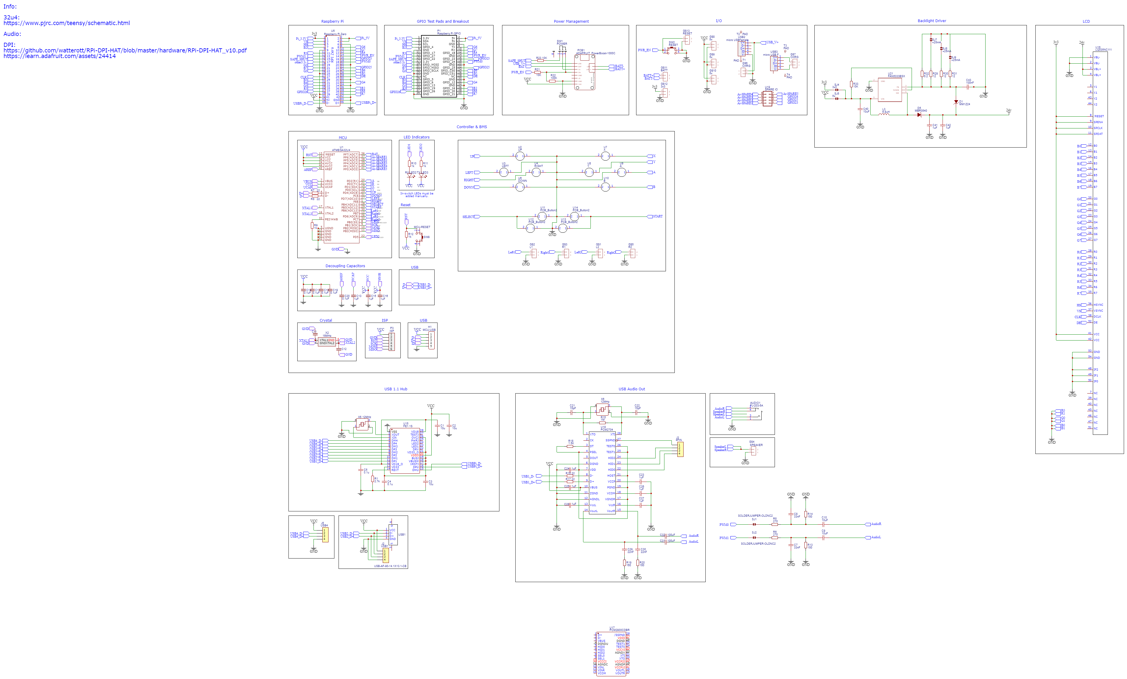

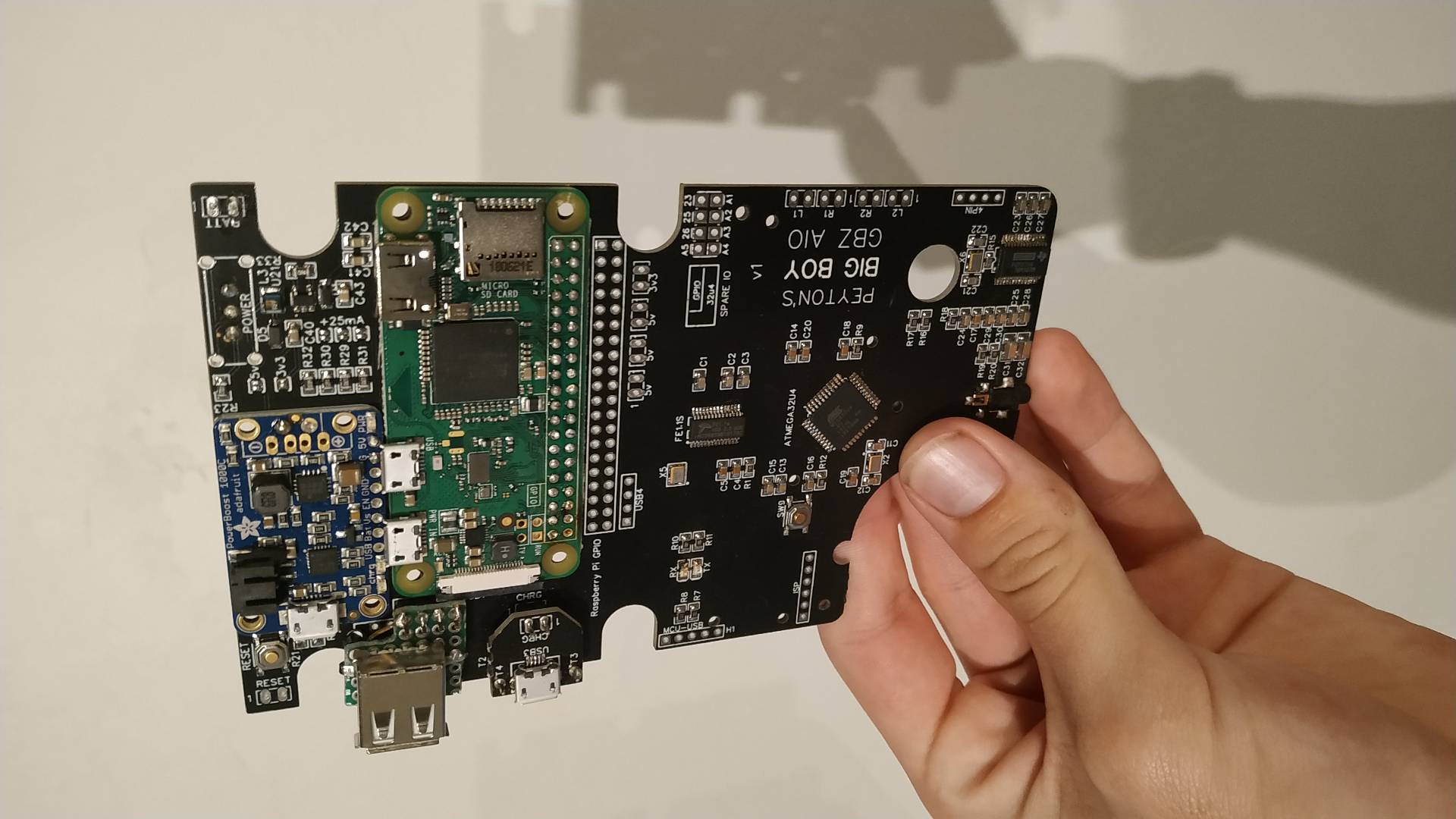
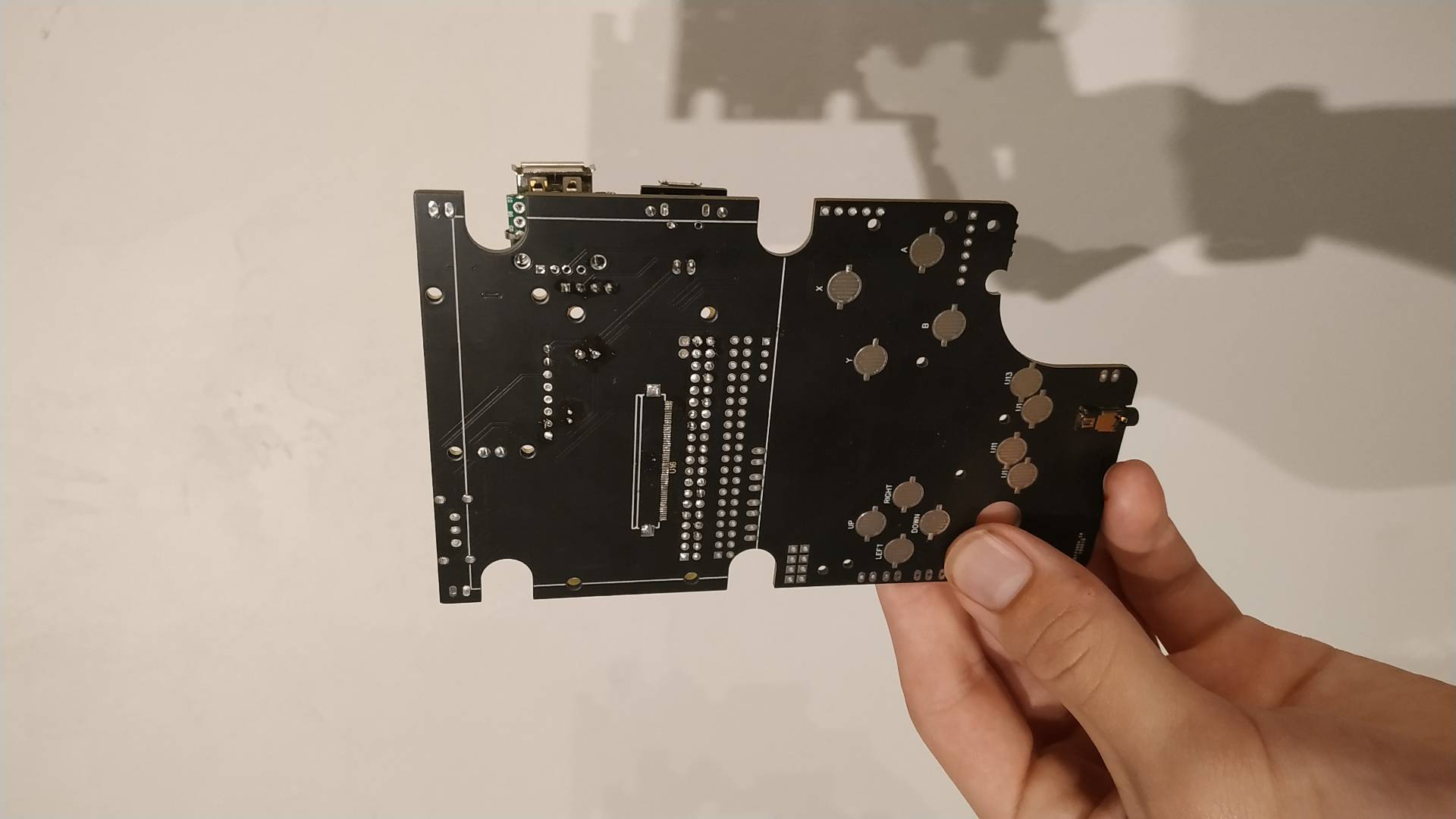
Version 1 included a custom all-in-one (AIO) PCB designed by Peyton. It housed interconnection between the Raspberry Pi, Microcontroller, LCD, battery, charge controller, USB hub, buttons, audio amp, speaker, and power switch. It was designed in EasyEDA and ordered from JLCPCB.
What is on the PCB:
- FE1.1S: A 4 port USB hub microchip
- The LCD backlight driver: 3.3V to 24V LED driver. Details
- Ribbon connector: to connect to LQ035NC111 LCD
- ATMega32u4 Microcontroller: Handles IO like buttons and battery levels,
- TI PCM2704: USB audio driver
- Adafruit Powerboost 1000C: Li-Ion battery charger capable of delivering 1000 mA to the system.
Software
I used much of the same software as the prototype.
Lessons Learned
- I think the ATMEGA32u4 controller needs pull up/down resistors since the membrane buttons need to be firmly pressed in order to be recognized as input.
- The Raspberry Pi gets uncomfortably hot after an hour or so, even with a small heatsink. It even thermally throttles for CPU-intensive games. Either updating to more efficient emulator cores or using a fan can resolve this issue, though a fan might drain power and make noise.
- I was unable to get the USB audio driver to work, it never became recognizable by the Linux OS, leading me to think it was not wired correctly.
- I assembled the PCB twice since the first one I did I managed to fry the SBC. Since it was soldered directly via the 40pin GPIO, it was virtually impossible to desolder it. This is a bad design choice.
Version 3 (Planned)
Hardware
PCB
The PCB has is planned to accommodate a different audio circuit, (hopefully working this time), and use a more open/standard method of connecting the PI GPIO. I am thinking of using POGO pins and the updated Raspberry Pi Zero 2 W which claimes to be 5 times as fast. I can push it even further and use the new Raspberry Pi Compute Module 3 which connects via a DDR2 SODIMM connector, or even a Compute Module 4, though I think that will be overkill for this project.
References
- Forum posting of prototype - https://sudomod.com/forum/viewtopic.php?f=43&t=8175
- Video post of prototype - https://www.reddit.com/r/raspberry_pi/comments/bp1dq8/my_raspberry_pi_zero_gameboy_build/
- TinkerBoy GBZ AIO board - https://www.tinkerboy.xyz/product/tinkerboy-controller-v3-0-game-boy-zero-aio-pcb-controller/
- Kite’s Circuit Sword AIO board - https://www.hackster.io/news/kite-s-new-circuit-sword-board-is-perfect-for-fitting-a-raspberry-pi-compute-module-into-an-89c6138044f1
- TinkerBoy Gameboy part store - https://www.tinkerboy.xyz/
- Backlight Driver circuit - https://sudomod.com/forum/viewtopic.php?f=43&t=3392&p=67889#p67979
- LQ035NC111 driver info - https://sudomod.com/forum/viewtopic.php?t=3553&start=10
- LQ035NC111 circuit - https://github.com/mattc74/DPI-Pi