A documentation of our home-built computer
Note: This page content is ripped from my dying wordpress site so most of the formatting is massaged from original.
Where it started
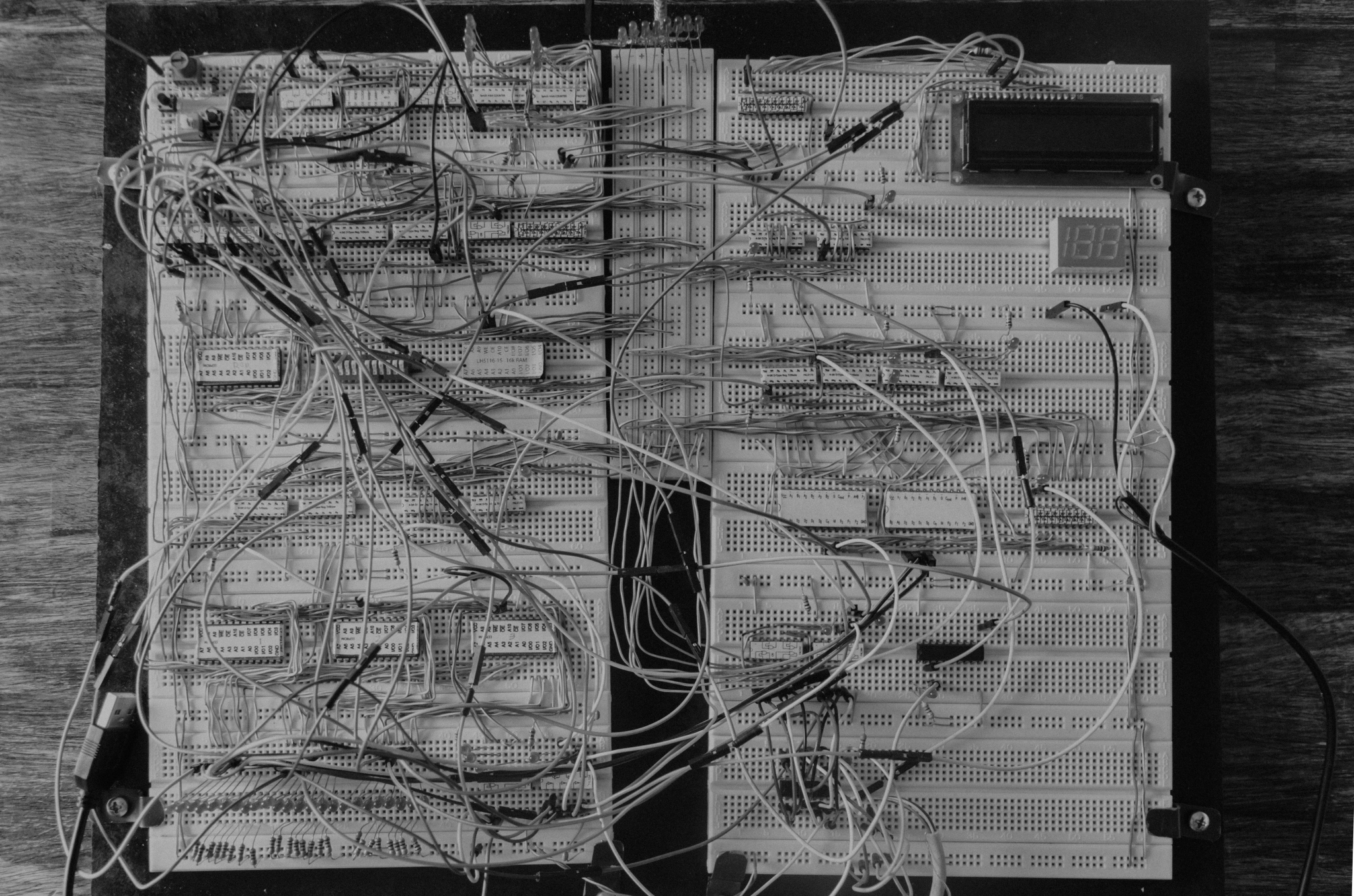
It started in the winter of 2015. We had a basic knowledge of circuits from our high school physics class and tech-savvy father. We had little to no knowledge of logic gates or integrated circuits. We needed something to do over winter break. Why not build a computer! Not just any computer, a computer made out of only TTL chips. A TTL chip is a small component that has many legs and is composed of numerous transistors. We had a couple of these laying around, but not nearly enough to build anything. So we decided to start off by designing it in a circuit simulator. After getting several circuit simulators, we decided to go with Proteus as our circuit designer because of its simple and most realistic logic platform.
General Information
BINARY COUNTING
A binary number is a code of 1s and 0s (in the light orange) at any length. It then translates to an integer, as represented in the dark orange box.
Binary is a number system form. It is represented by 0s and 1s. This number system is ideal for logic computers since logic gates read either low or high voltages. Therefore, you can relate low reading to the number 0, or high voltage to the number 1, and then use binary code to make any number.
TTL Data
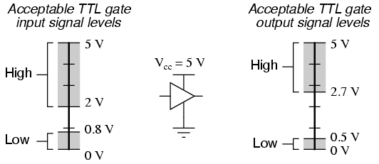
TTL stands for Transistor-Transistor Logic. It is a type of Integrated circuit logic design that uses voltage ranges to act as inputs. For TTL (unlike CMOS), 0V (or GND) acts as data bit 0 and about 3-5V is data logic 1
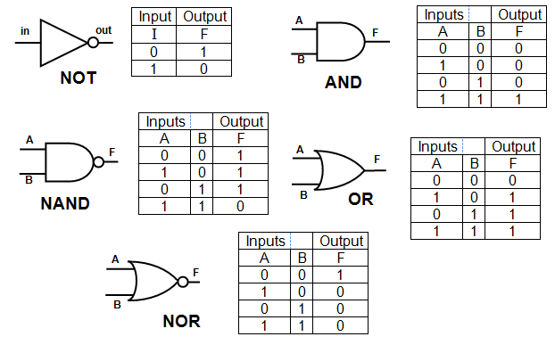
Logic Gates
Components
CLOCK and COUNTER
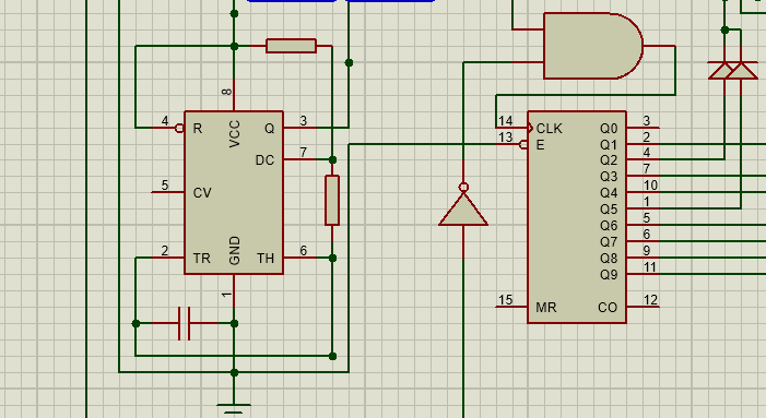
To essentially set the pace for the computer, we need a clock. To the right is an example of the clock circuit we used for ours. It is a 555 paired with a 4017. The 555 is an oscillator and the 4017 is a step counter.
RAM, ROM, and Memory Address Register (MAR)
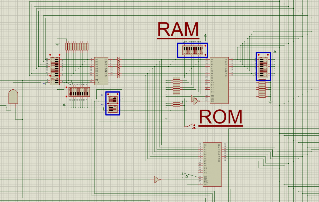
The computer’s program is run off of a pre-programmed ROM. The ROM holds binary data, or assembly code, that is unique to this computer. The ram holds exactly what it stands for, Random Access Memory. It is Readable and Writeable. The MAR holds the address line for the RAM/ROM while data is written/read from the chips.
Control Logic
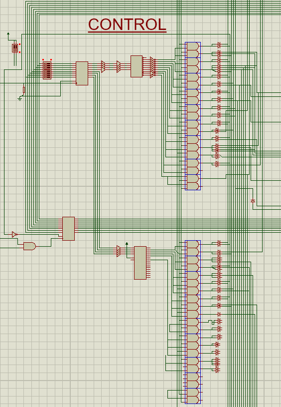
The control logic is like the brain of the computer. It receives and deciphers the assembly language from the ROM and tells what the rest of the computer to do.
*Revision: On our final build, we replace the numerous and gates with 3 ROMs for simplicity.
Arithmetic Logic Unit (ALU)
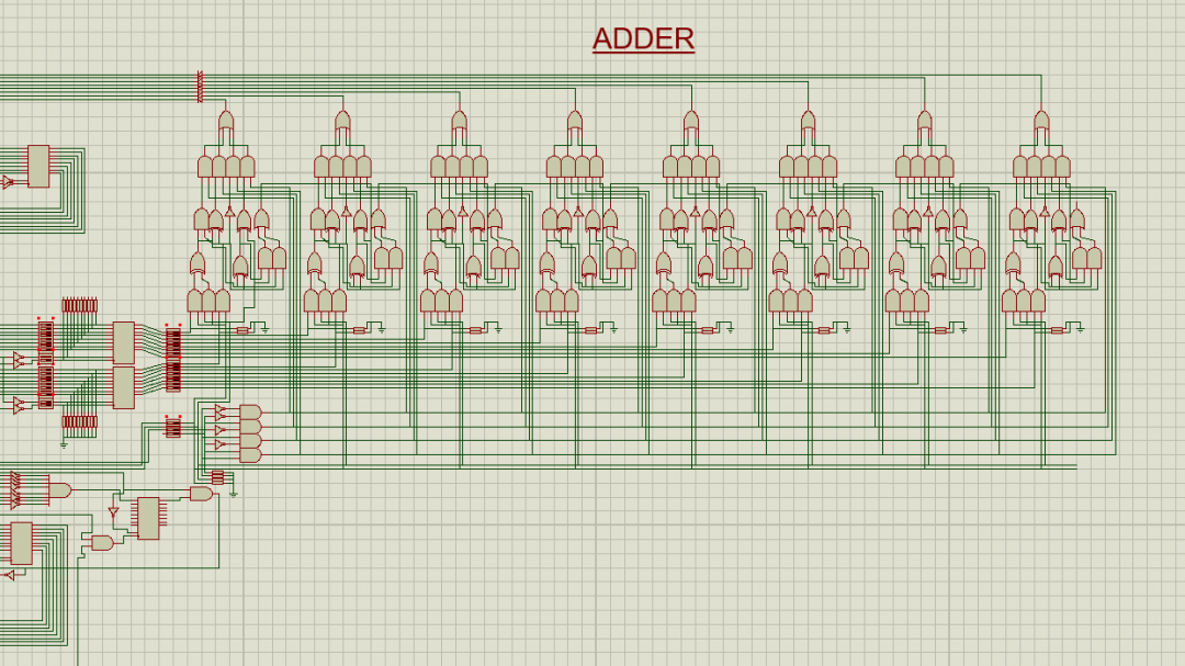
This part of the computer does all of the adding, subtracting, comparing, and miscellaneous arithmetic functions.
*Revision: On our final build, we replace the numerous logic gates with 2 4-bit ALU ICs
Registers
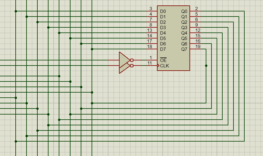
The register is like a miniature RAM that only holds one byte of data (8 bits)
Display
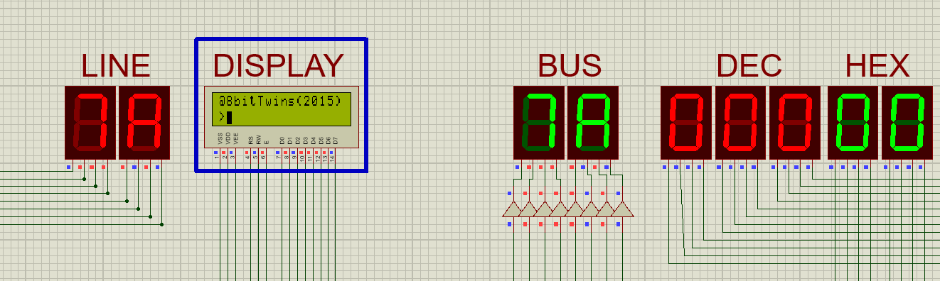
The display is a small screen to communicate with the user.
Goals
We are not done yet. We plan to continue the project with these in mind:
- More Memory: We want the computer to be able to hold more memory to run more intensive software. To do this we will either expand it to 16-bit addresses or rewire it to take two 8-bit addresses and put them together as a single 16-bit.
- Self Programmable: We want to program the computer so that it can program itself without the help of another computer. This can only be done by expanding the ROM.
- Prototype it onto a PCB. This will allow us to travel with it without the fear of wires coming out.
Resources
Huge thanks to these inspirations and resources: Essentially, the project was inspired by Ben Eater’s videos of an 8-bit processor.
Eater’s design was then converted into schematic by Oded who has put a lot of information about 8-bit computers and how they work on his site, which is definitely worth a look at:
Other information: